 English
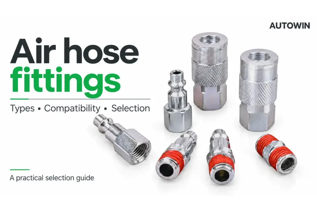
An air fitting can have the right thread and still be the wrong connection. Selecting it requires separate checks of the coupling profile, body size, end connection, hose or tube dimensions, and operating conditions. A plug that enters a socket is not, by itself, evidence of an approved match.
This guide explains the main types of air hose fittings and how to specify them for a workshop, production line, equipment assembly or distributor range. Start with the connection you need to make, then work through compatibility and performance before comparing prices. The result should be a clear specification that another person can use to order the same part again.
Map the air connection from the supply to the tool
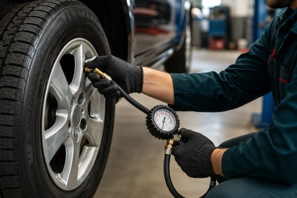
Trace one complete air path before selecting individual components. A typical arrangement includes a regulated supply outlet, a hose assembly, a quick coupling and a tool inlet. Your layout may place quick couplings at different points or use fixed connections. Each junction has its own sealing and retention method.
For example, a coupler can connect to a hose end through a threaded joint while its socket accepts a removable plug. The plug may then screw into the tool. The quick coupling and the threaded joints are separate interfaces: matching one does not establish that the others are correct.
| Connection in the air path | What joins the parts | What to specify |
|---|---|---|
| Coupler to removable plug | A matching profile, seal and locking mechanism | Profile family, body size and approved mating parts |
| Threaded fitting to a port | Compatible threads and the intended sealing feature | Thread standard, nominal size, gender and seal arrangement |
| Hose to a barb | A suitable hose over the barb with the approved retention method | Hose ID, construction, barb specification and retention system |
| Tube to a push-in fitting | A gripping mechanism and a seal around the tube | Tube OD, material, tolerance and permitted service conditions |
This connection map is also useful when a fitting leaks. Air escaping from a threaded joint points to a different investigation from leakage at a plug seal or a tube entry. Replacing every part with a larger connector can leave the original mismatch unresolved.
Recognize the main air hose fitting types
Quick couplers and plugs
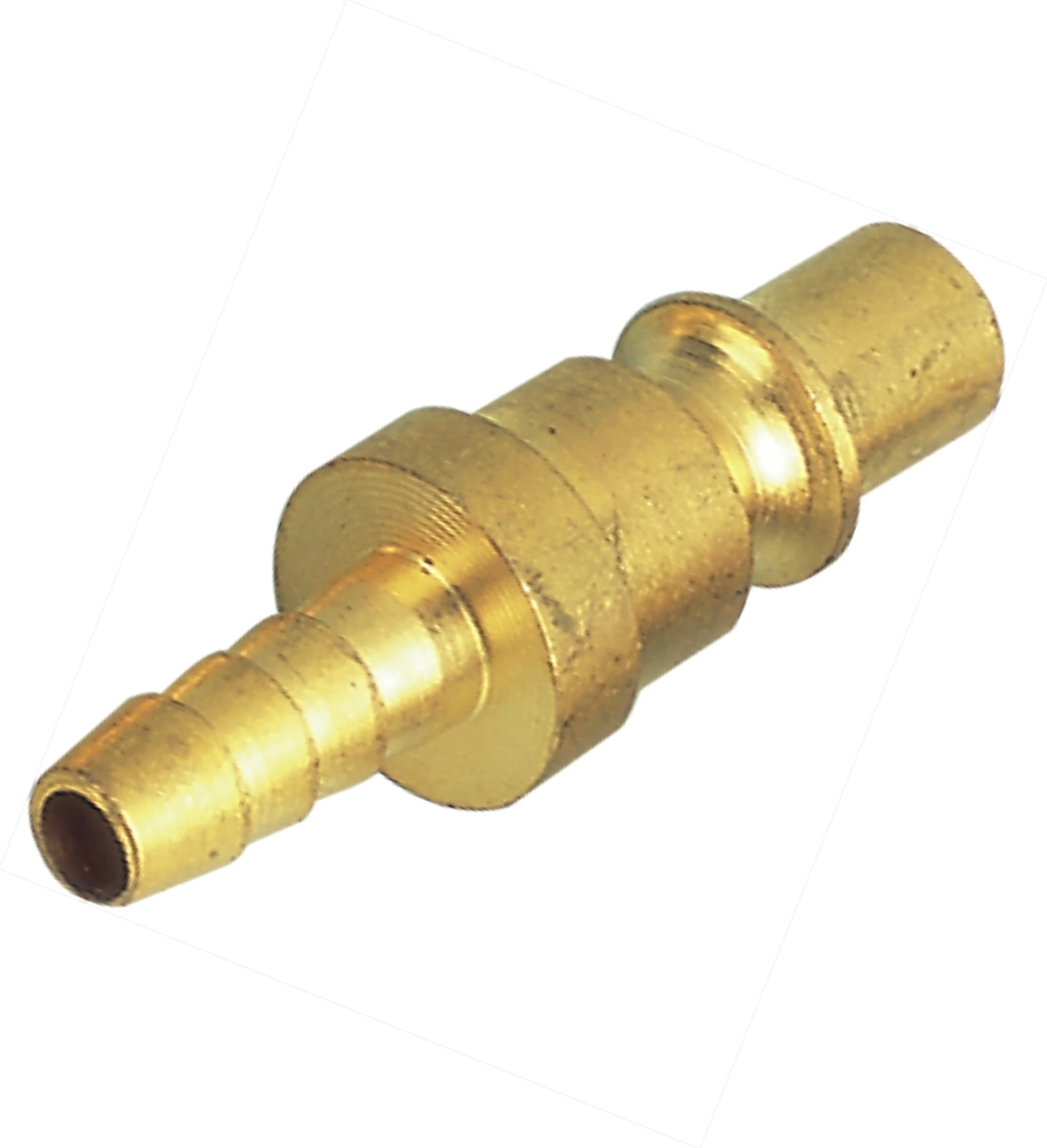
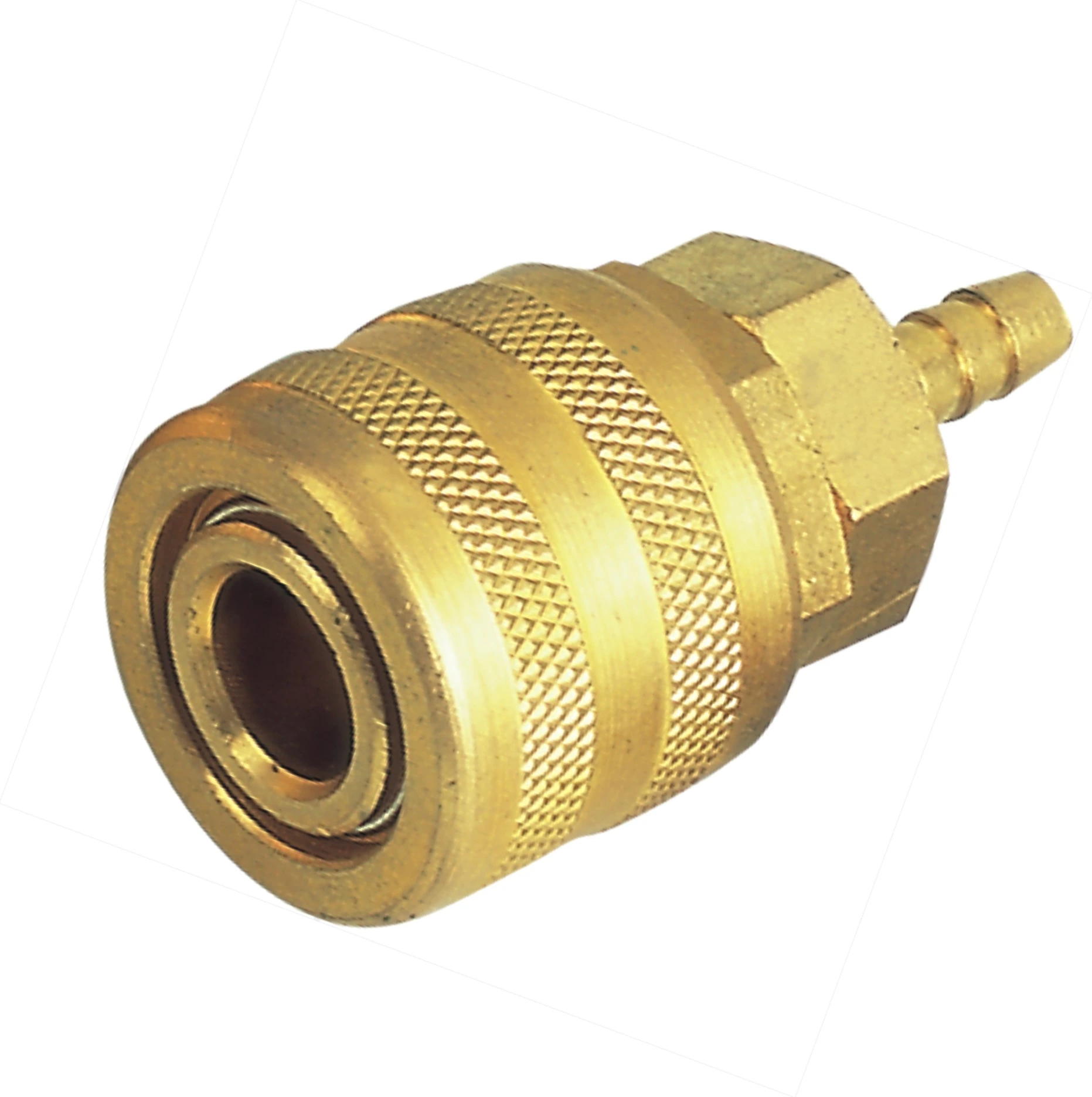
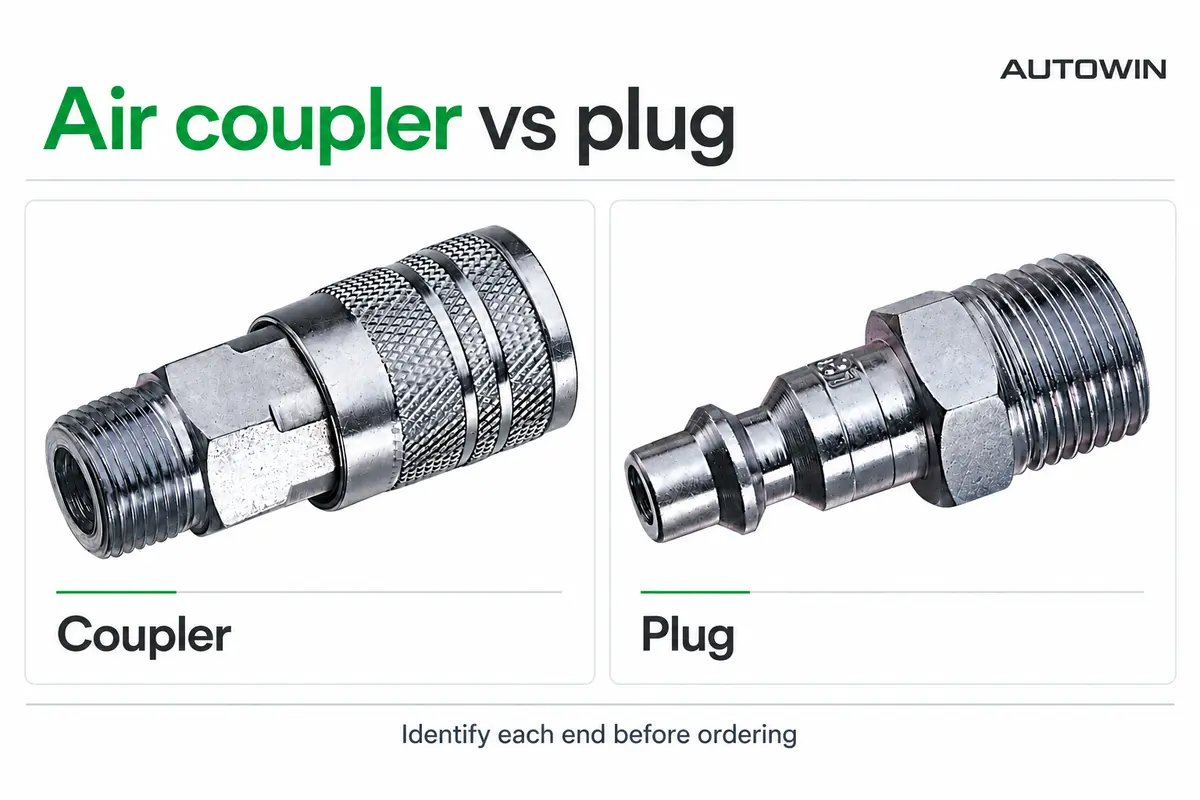
A quick coupling provides a detachable connection between a socket, often called the coupler, and a mating plug. Common shop-air versions have a valve in the socket that closes when the plug is removed. Other constructions have different valve arrangements, so the component drawing and operating instructions matter.
The words male and female can describe either the coupling interface or the threaded end. A socket can have male threads, and a plug can have female threads. Use the complete description when ordering; our air coupler vs plug guide shows how to distinguish these combinations.
Threaded adapters and pipe fittings
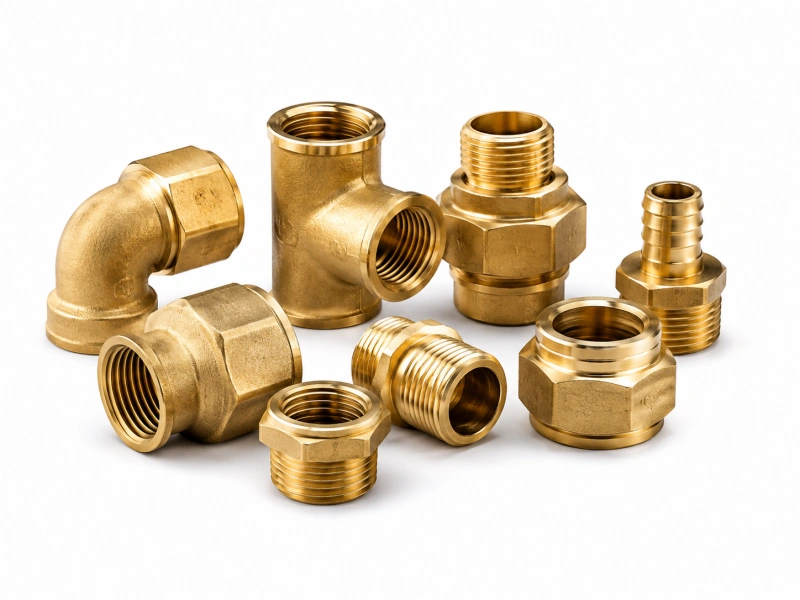
Adapters connect compatible ports with different approved end configurations. Elbows change direction; tees and manifolds create branches. They solve layout problems, but every extra joint adds another place to inspect for sealing, restriction and mechanical loading.
Choose adapters from the actual port specifications. NPT, NPTF, BSPP, BSPT and metric designations should not be reduced to a fractional size alone. The thread form and sealing geometry determine which parts belong together. A fitting that starts to screw into a port may still be incorrect.
Barbed and mechanically retained hose ends
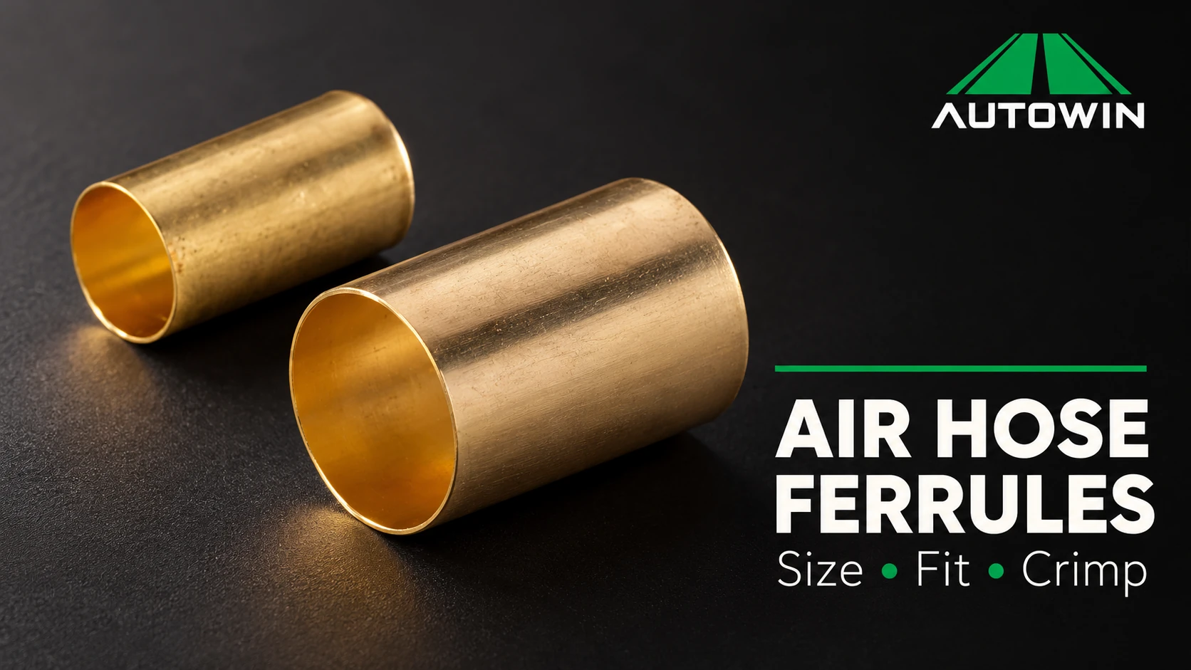
A hose barb enters the hose bore. The hose material and construction, barb geometry, and specified retention method must form a suitable assembly. Depending on the product, retention may involve an approved clamp, a crimped ferrule or a dedicated reusable construction. These methods are not interchangeable assembly instructions.
A common hose ID does not establish that two hoses accept the same ferrule or crimp setting. Their cover thickness, reinforcement and deformation during assembly can differ. Dixon’s crimp guidance explicitly treats hose construction and outside diameter as relevant variables. [1]
Push-in pneumatic tube fittings
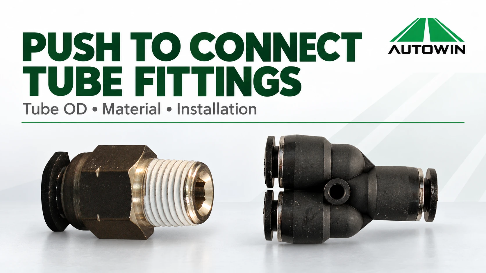
A push-in fitting grips a specified tube and seals against its outside surface. Selection normally starts with tube outside diameter and the permitted tubing material. The SMC KQ2 ordering tables, for example, identify tubing OD separately from the connection thread. [4]
The term “push-to-connect” can also describe an automatically engaging quick coupler. Check what is being inserted: a tube end or a shaped plug. Similar wording does not make these two connection systems interchangeable.
Identify the quick-coupling profile
Air hose connector types include several distinct plug profiles. Industrial interchange, automotive or Tru-Flate, ARO and Lincoln are common names in North American catalogs. European and other regional profiles add further possibilities. High-flow product names can describe several designs rather than one universal interface.
The profile includes the shape and dimensions of the plug nose, sealing area, shoulder and retaining groove. These features must work with the socket’s seal, locking elements and valve. A similar-looking external sleeve tells you little about the interface inside.
| Catalog description | Useful starting point | Confirmation still required |
|---|---|---|
| Industrial interchange | The listed industrial profile and body-size family | The exact plug and socket series accepted by the manufacturer |
| Automotive or Tru-Flate | The automotive interchange profile | Correct body size and matching socket specification |
| ARO or Lincoln | The manufacturer’s profile drawing | The specific family and dimensions, not a generic letter code |
| High flow | Documented profile and flow performance | Compatibility and test conditions for the exact configuration |
| Universal coupler | An explicit list of accepted plug profiles | Supported sizes, restrictions and performance for each pairing |
Parker’s interchange guide separates industrial, Tru-Flate, ARO, Lincoln and other profiles. Its series names are specific to Parker’s product range. Another manufacturer’s letters may mean something different. Use a documented cross-reference with the correct body size, rather than translating a letter from memory. [2]
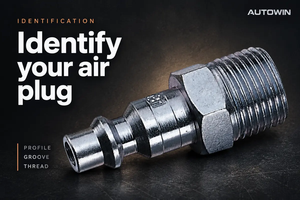
For a side-by-side decision, see industrial vs automotive air fittings. If the existing part has no readable marking, follow the unknown air plug identification procedure before choosing a replacement.
Guides to Common Air Coupling Profiles
Continue with the guide for the profile or socket type under review:
Separate body size from thread and hose size
A single assembly can legitimately contain several different size labels. “1/4 inch” might identify a quick-coupling body class, a nominal pipe thread, a hose bore or an actual tube outside diameter. These labels answer different questions.
In a coupling catalog, body size identifies a product family or interface class. It is not necessarily the measured diameter of the outside housing or the plug tip. Thread size describes an end connection. Hose ID describes the bore of a hose; tube OD describes the outside diameter used by many push-in fittings.
Consider an illustrative specification for a plug with a 1/4-inch body and a 3/8-inch hose barb. The first size identifies the coupling family; the second identifies the intended hose bore, subject to the approved hose construction. It does not follow that the plug needs a 3/8-inch-body socket.
For threaded parts, nominal pipe size also differs from a caliper reading across the male threads. Identify taper, diameter, pitch and the sealing arrangement together. Swagelok’s identification procedure treats thread identification and end-connection identification as related but separate steps. [3] Use the air hose fitting size guide to record each dimension in its own field.
Match flow performance to the application
A pressure rating tells you about the permitted operating pressure under specified conditions. It does not tell you how much air will reach a tool while it is running. A coupler can have an adequate pressure rating and still create excessive pressure loss at the required flow.
Compare flow data using the same inlet pressure, allowed pressure drop, reference conditions and coupling configuration. Record whether the figure applies to a complete coupled pair, a particular plug, or a different test arrangement. A CFM value without those details cannot establish that one product will outperform another in your system.
Look beyond the coupling as well. Hose length and bore, small adapters, valves, filters and regulators all contribute to the supply path. A high-flow coupler may help when that coupling is the relevant restriction; it will not remove a bottleneck somewhere else. Check conditions at the point of use while the application is drawing air.
Our air coupler data-sheet guide explains which pressure and flow fields to collect before comparing quotations. Keep the original units and conditions alongside any conversions so the comparison remains traceable.
Check pressure temperature and materials together
Define the maximum expected service pressure, including relevant operating transients, and the temperatures the components will actually experience. Ambient temperature and the temperature of the compressed air may differ. The acceptable combination must be supported for the selected configuration.
Review the socket, plug, hose, hose attachment and any adapters as an assembly. The lowest applicable component or connection limit constrains the assembly, and component ratings alone do not prove that the assembled combination is approved. Burst pressure is not an operating setpoint or a suggested field-test pressure.
Material descriptions need similar care. “Brass coupler” may describe the housing while the sleeve, valve, balls, springs and seals use other materials. Ask for the material of the parts relevant to corrosion, wear and compatibility with the actual air supply and environment.
Include condensate, compressor lubricant, cleaning chemicals and outdoor exposure in the application description where relevant. A material that suits one service may not suit another. Do not extend ordinary shop-air product suitability to oxygen, breathing-air, medical or other special systems without the specific approvals and documentation those applications require.
Choose the hose and attachment as one assembly
Start with the hose manufacturer’s intended service and connection system. Record the hose ID and OD, material, reinforcement, working conditions and minimum bend-radius requirement. Then match the end fitting and retention method to that construction.
For a crimped assembly, the ferrule, fitting, hose and approved crimp specification belong together. For a reusable fitting, use the assembly method and permitted hose range for that particular design. A field replacement based only on matching the visible outside diameter is not enough.
For pneumatic tubing, confirm the fitting’s OD tolerance and material requirements. A tube can be easy to insert yet still fail to seal or retain correctly if it is undersized, oval, scratched or made from an unsuitable material. Preserve the difference between flexible hose and precision-sized tubing in the bill of materials.
Installation space also affects selection. Allow access to the coupling release mechanism and wrench flats, protect the connection from excessive side loading, and route the hose so normal movement does not pull continuously on the joint. These are assembly-design questions that a catalog pressure number cannot answer.
Plan installation and validation before release
Use the installation and disconnection instructions for the selected components. Before inspection, replacement or an uncertain compatibility check, isolate the relevant supply and verify that stored pressure has been relieved. Do not force a mismatched plug or use a live air line as a profile-identification test.
Confirm the threaded sealing method before applying tape, liquid sealant or a gasket. Some products have pre-applied seals; some end connections seal away from the threads. The correct tightening method depends on the actual thread, material and manufacturer instructions.
For an OEM assembly or a wholesale kit, define sample acceptance before purchasing volume quantities. The review should establish that the specified parts match, operate as intended and satisfy the agreed leak, retention and performance requirements. Testing must follow an approved procedure with suitable equipment and protection.
Keep the accepted drawing revision, part numbers and assembly specification with the approval record. If a later substitution changes the hose construction, seal material or mating plug, review the affected requirements again instead of treating the original sample approval as blanket permission.
Investigate problems at the interface where they occur
| Observed problem | First questions to investigate |
|---|---|
| Plug will not lock | Are profile and body size correct? Is there damage, contamination or an obstructed mechanism? |
| Leak at the threaded joint | Do the thread standard, sealing feature and assembly method match? |
| Leak around the connected plug | Is the plug approved for the socket? Are the sealing surfaces and seals in suitable condition? |
| Tube or hose moves out of its fitting | Are dimensions, material, insertion or assembly method, and retention components correct? |
| Tool performance falls during use | What are the supply pressure and pressure losses at the required operating flow? |
These questions organize diagnosis; they are not instructions to dismantle a pressurized connection. Record the location and conditions of the problem, then inspect under the equipment’s isolation procedure. A clear failure description is more useful to a supplier than “the fitting is bad.”
Write an OEM or wholesale purchasing specification
A purchasing description should allow a pneumatic coupling manufacturer to identify both the mating interface and the operating requirement. Include the requested connector family, body size and each end connection, followed by material and performance conditions. Add a drawing or a known mating-part reference wherever possible.
| RFQ field | Information to provide |
|---|---|
| Connection | Coupler or plug, profile, body size and mating-part reference |
| Ends | Thread standard, size and gender, or hose ID and tube OD |
| Service | Medium, maximum operating pressure, temperature range and required flow conditions |
| Construction | Relevant body, sleeve and seal materials; required finish |
| Acceptance | Drawing revision, dimensions to inspect and agreed functional verification |
| Supply | Order quantity, annual demand, kit contents, marking and packaging requirements |
For OEM air couplers, specify which features are fixed and which can be proposed by the supplier. A custom logo or finish is a different scope from a custom mating geometry. For wholesale assortments, label every compartment with a complete specification so similar-looking parts do not become mixed inventory.
Explore AUTOWIN’s pneumatic quick connect fittings to identify the relevant product family. For a drawing-based or private-label program, send the connection details, operating conditions and expected quantity through our OEM and ODM project review.
Common selection questions
Are all quarter-inch air fittings compatible
No. The size may describe a body class, a pipe thread, a hose ID or a tube OD. Even two quick couplings with the same body-size label can use different profiles. Confirm the complete interface and operating specification.
Does a universal coupler accept every air plug
No. Universal describes the profiles listed for that product. Check its accepted plug families and sizes, and any operating restrictions for each combination. An unlisted profile should remain unapproved until the manufacturer confirms it.
Should a higher pressure rating decide the purchase
Only after the required operating limits are satisfied. Compatibility, flow performance, release operation, materials and the hose attachment still need evaluation. A higher pressure number alone does not establish a better connection for the application.
What information makes a replacement enquiry easier
Provide clear photographs of both ends, readable markings, measured dimensions, the existing mating-part reference and the application conditions. If the profile cannot be confirmed, discuss a documented matched pair rather than requesting an assumed equivalent.
Related reading: connection operation and pressure control
- Safety Air Couplers: How Vent-Before-Release Designs Work
- Manual vs Push-to-Connect Air Couplers: Which Operation Fits Your Workstation?
- Disconnecting an Air Coupler: Control Trapped Pressure First
- Single-Shutoff vs Double-Shutoff Air Couplings: What Happens After Separation?
- Straight-Through Air Couplers: Check the Valve Arrangement Before Ordering
- Hose-Burst Protection vs Safety Air Couplers: Two Different Jobs
Technical references
- Dixon Quick Coupling Catalog 2026. Quick-coupling selection, installation and hose-attachment guidance. PDF pages 2, 15–20.
- Parker Pneumatic Interchange Guide. Pneumatic plug profiles and associated coupler families. PDF pages 1–2.
- Swagelok Thread Identification. Thread and end-connection identification. PDF pages 5–9.
- SMC KQ2 KJ One Touch Fittings. Tube outside diameter, fitting structure and ordering fields. PDF pages 4–5.