 English
To disconnect an air coupler safely, first identify where compressed air may remain and follow the instructions for the exact coupling and equipment. Stopping the compressor does not establish that the hose, receiver or downstream circuit is pressure-free. A shut-off component may stop incoming air while leaving a separate volume charged.
The right preparation is a pressure map: identify the section being disconnected, how it is isolated, how that section is exhausted and how its state is verified. The points below help maintenance teams build that review. They do not replace the machine’s approved operating or energy-isolation procedure.
Separate routine changeover from servicing
A routine tool change using a documented safety coupling is different from unscrewing a fitting, replacing a seal or dismantling a hose assembly. A coupling may have an operating sequence intended for changeover, while maintenance requires additional isolation of the equipment and its energy sources.
For service work, competent personnel should apply the site’s approved isolation procedure, control possible re-energization, release stored energy through the designated means and verify the condition of the relevant section. Keep equipment supported where loss of pressure could allow movement. Do not treat a quick-release socket as a substitute for the required isolation arrangement.
The supplied Dixon catalogue recommends shutting down and relieving pressure when investigating a coupling leak. It also warns against striking coupling valves to release trapped pressure and striking sleeves with tools. Those are particularly useful limits when a connection feels difficult to release.
Map the volumes that can retain air
| Location to identify | Question to resolve | Evidence to record |
|---|---|---|
| Supply branch | What prevents further air supply? | The approved isolation point and procedure |
| Hose being removed | Which route exhausts this volume? | The specified exhaust device or coupling function |
| Tool or downstream circuit | Could a valve retain pressure separately? | Equipment instructions and circuit information |
| Verification point | Does the check represent the section being opened? | The approved pressure-verification method |
| Mechanical load | Could depressurization permit movement? | The equipment’s required support or restraint |
A gauge upstream of a closed valve may not indicate the condition on the other side. Similarly, silence at an exhaust is not enough by itself to prove that every connected or isolated volume is discharged. Verification must correspond to the part of the circuit being worked on.
Read the coupling instructions before moving the sleeve
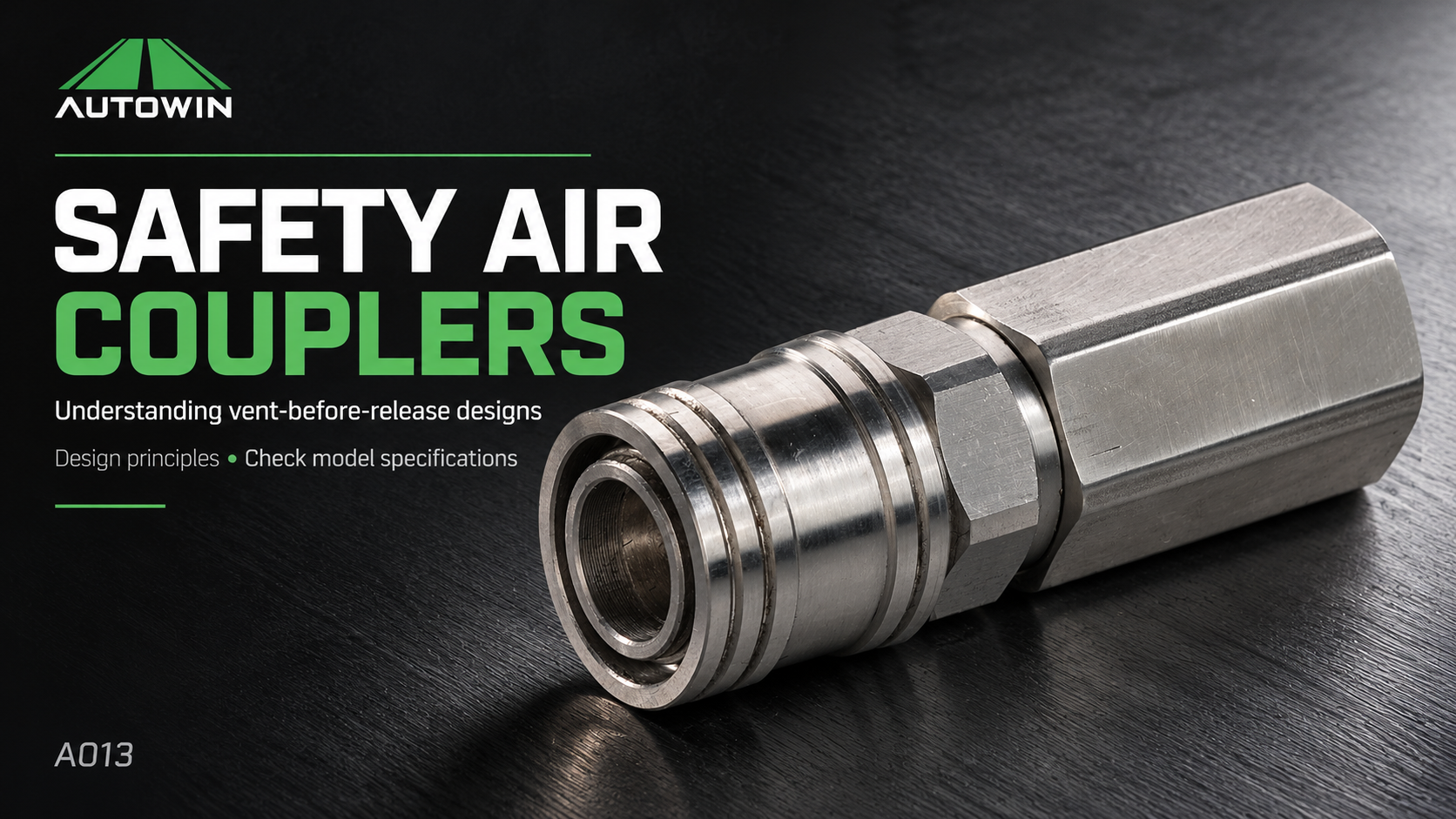
Air hose quick connectors do not all disconnect in the same way. A conventional shut-off socket, a vent-before-release coupling and an unvalved connection can leave different pressure conditions during separation.
Festo’s NPHS documentation describes exhausting the connector side before unlocking. CEJN’s eSafe brochure also describes venting before disconnection. Neither example authorizes applying one brand’s sleeve action to an unidentified fitting. Confirm the actual part and approved mate before relying on a particular function.
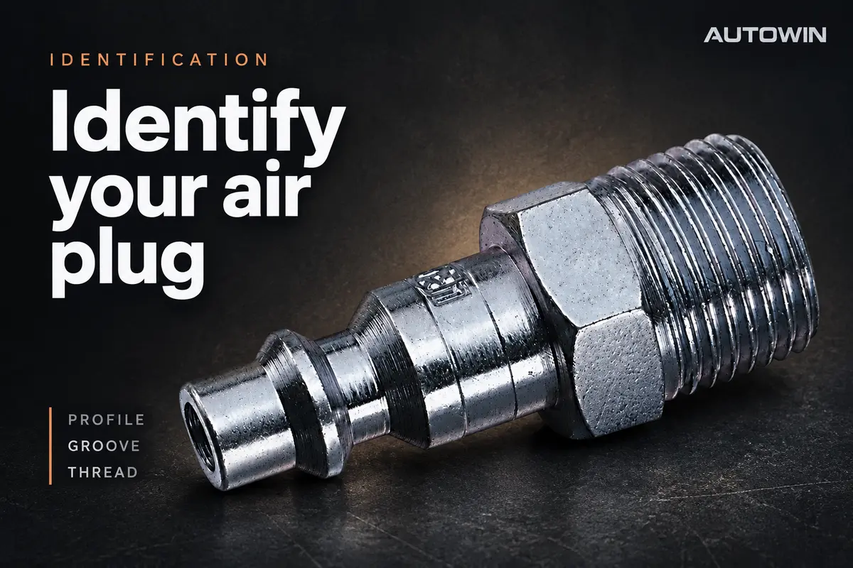
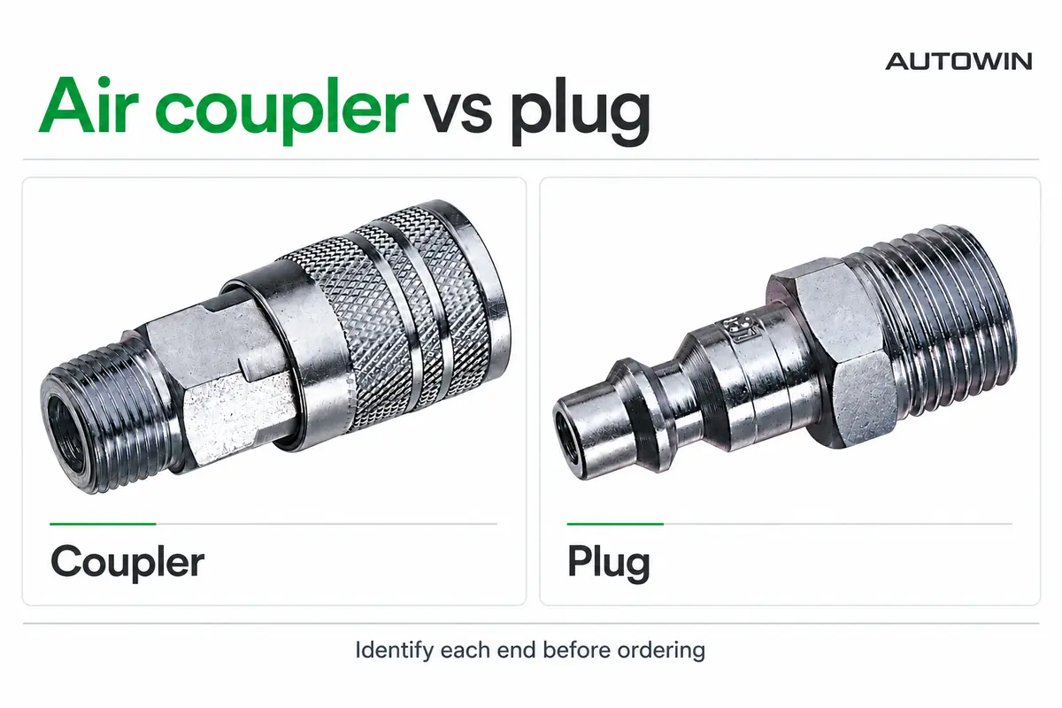
If identification is uncertain, use the air quick-connect plug identification guide as a documentation starting point. A photograph and dimensions can help identify an interface; they cannot establish that a safety mechanism is present or functioning.
When the connection will not release
Stop the changeover if the sleeve is damaged, the mechanism behaves unexpectedly or the pressure state cannot be verified. Follow the applicable isolation and fault-handling procedure. Do not increase force, strike the coupling or loosen the threaded end to create an improvised exhaust path.
Record the part numbers, visible condition and circumstances for the maintenance review. A damaged nose, contamination, incompatible parts or a failed mechanism may need investigation, but the observed symptom alone does not prove which cause is responsible. Replace or service parts only as permitted by their manufacturer.
The coupler and plug terminology guide helps separate a problem at the quick connection from one at the threaded hose end. That distinction improves a fault report and avoids replacing the wrong interface.
Make the instruction usable at the workstation
A practical instruction identifies the approved connection, the location of the relevant controls, the verification required and the action to take when something is wrong. Use photographs of the installed equipment when preparing a site procedure. Keep replacement-part information alongside the operating instruction so an unnoticed substitution does not invalidate it.
For OEM air hose assemblies, ask for documentation of the complete configuration and the disconnecting function, not just a component catalogue page. An industrial air coupling supplier should be able to clarify which instructions apply to the proposed model and which equipment-level decisions remain with the system designer.
Maintenance questions
Can I just switch off the compressor?
That alone does not prove that stored air has been removed. Receivers, branches and isolated sections may remain pressurized. Use the approved isolation, release and verification procedure for the relevant equipment.
Should I press the plug valve to empty the line?
Do not improvise a venting method. Use the designated exhaust arrangement and the manufacturer’s instructions. Never strike a valve or sleeve to force pressure release.
Does a safety coupling discharge every part of a machine?
No. Its function applies to the volume served by its exhaust path. Other isolated volumes and other energy sources must be addressed by the equipment procedure.
For selection context, see the air hose fittings guide. When reviewing replacement quick disconnect air fittings, include the required release behaviour and mating-part identification. Send assembly requirements through AUTOWIN’s OEM enquiry page.
Download this guide
Keep the complete guide, comparison table and technical references for your next specification review.
Download PDF (4 pages · 3.9 MB)
Technical basis
- Dixon 2026 Quick Coupling Catalog, physical PDF pages 15–16: selection and safe-use principles.
- Festo NPHS catalogue, physical PDF page 2, and CEJN eSafe brochure, physical PDF page 5: product-specific vent-before-release examples.