 English

Planning an Air Hose Splitter for Multiple Tools – PDF, 4 pages
An air hose splitter distributes one compressed-air supply to several outlets. It does not create additional compressor capacity or guarantee equal performance at every connected tool. Select it by the demand that occurs at the same time, the common supply path and the way each branch will be connected and isolated.
For a workbench with several tools, the number of outlets is easy to count. The harder question is whether those tools run together and whether the supply can support them at their required inlet conditions. Answer that question before choosing a compact splitter or a larger manifold.
Map the tools before counting the ports
List each tool’s required operating pressure, air consumption and expected operating pattern using its manufacturer’s data. Identify which operations can overlap. Tools that are connected but idle do not have the same demand pattern as tools that run continuously together.
When evaluating an air compressor splitter, compare the compressor’s delivered-air specification at the relevant pressure with the intended duty. Do not substitute tank volume or a pressure-switch setting for delivered airflow. Include other users of the same supply in the assessment.
For a production station, a simple equipment schedule is a useful starting point. Where demand information is uncertain, obtain measurements or an engineering assessment before committing to the distribution layout.
| Branch record | Information to collect |
|---|---|
| Tool or process | Manufacturer and model, with required inlet conditions |
| Operating pattern | Continuous, intermittent or alternating use |
| Overlap | Which other branches may operate simultaneously |
| Branch hardware | Hose dimensions, connectors and any regulator or valve |
| Acceptance check | Required performance at the tool under the intended combined load |
Read inlet and outlet sizes separately
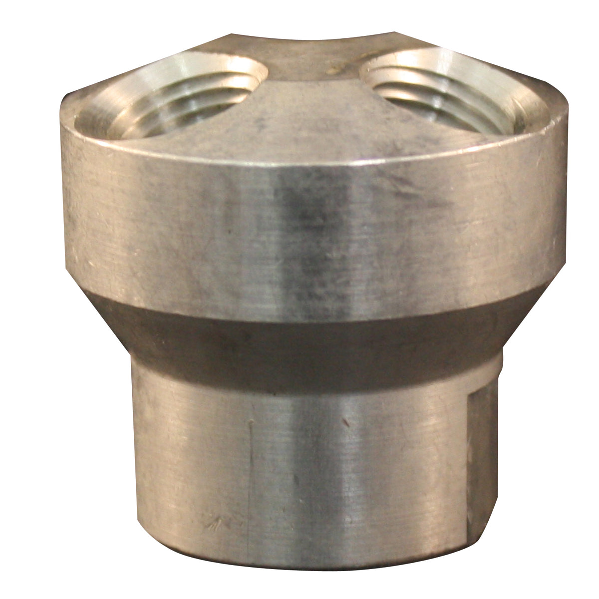
A manifold can have a larger common inlet than its branch outlets. Coilhose’s catalog illustrates different manifold layouts with separate supply and outlet specifications. It also distinguishes compact, straight and other configurations with different mounting arrangements.
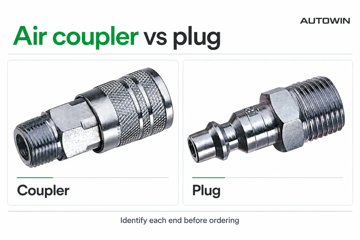
Record every connection in the proposed air hose manifold. Identify the inlet, each outlet and any unused port that needs an approved closure. Confirm the thread standard and sealing method for the actual model.
A large inlet marking alone does not establish the complete assembly’s airflow. The supply hose, upstream connector, internal passages and branch components all belong to the flow path. Review available flow data under stated conditions, then assess the assembled installation.
Our guide to pneumatic connection sizes helps distinguish the port description from hose dimensions. Use the data-sheet review guide when comparing performance figures for the connectors fitted to the manifold.
Choose a layout that can be supported and serviced
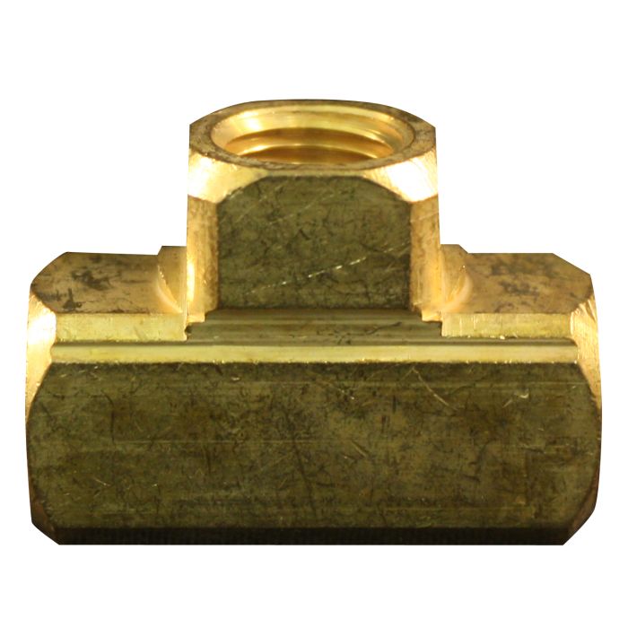
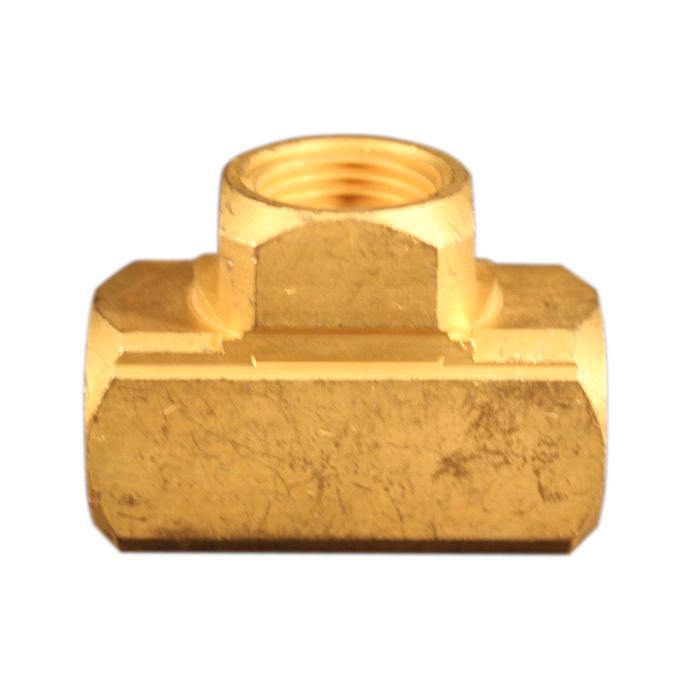
A compact tee can suit a small branch arrangement. A mounted air line manifold may be easier to organize at a fixed workstation with several outlets. Coilhose’s catalog describes manifold applications including assembly stations and distribution to multiple locations from a single supply.
Consider where the hoses will pull on the assembly. Review mounting provisions, available wrench access and clearance around couplers or valves. A layout that looks compact in a catalog can become crowded once all branches are connected.
Label the outlets according to their actual function. Where different tools require different branch settings, identify the associated regulation and isolation components on the drawing. A distribution block does not provide those functions unless the specified assembly includes them.
Plan isolation for each service task
Determine how a branch will be made safe before a hose or tool is changed. An ordinary air line splitter should not be assumed to include shutoff valves, pressure relief or a safe-disconnection mechanism. Confirm the function of each installed component.
Identify where pressure can remain after a valve closes. A shutoff device can isolate a section while leaving air trapped in it. The service procedure must address that retained pressure before the connection is opened.
Our article on disconnecting a line with trapped pressure explains the issue. Apply the equipment manufacturer’s procedure and the site’s isolation requirements to the complete distribution arrangement.
Evaluate all intended operating combinations
A single tool working correctly does not prove that the system will support every intended combination. During commissioning, assess the station with the relevant branches operating together. Record pressure at the appropriate point near the tool and check the tool’s required performance.
If performance changes when another branch starts, investigate the shared supply and the affected branch. Possible areas for assessment include compressor delivery, the common hose, connectors, regulation and branch demand. The observation does not automatically identify the splitter as the cause.
Keep the accepted configuration on record. Adding another outlet later can change the demand pattern, so expansion should trigger a review of the supply and intended simultaneous use.
Specify manifold assemblies for OEM or wholesale supply
An OEM request should define inlet and outlet threads, port count, mounting geometry, installed accessories and service conditions. State whether the quotation covers a bare block or a completed assembly. Ask the manufacturer to identify the supplied components and the applicable inspection or test documentation.
For wholesale distribution, distinguish bare splitters from assemblies supplied with couplers, plugs or valves. The product description should make those contents explicit. Also identify whether customers must select a particular mating connection for the outlets.
AUTOWIN’s 3-in-1 hose manifold listing provides a starting point for a distribution-component inquiry. Send a branch layout and tool schedule with your request so the quotation can be checked against the actual connection and installation requirements.
Technical references
- Coilhose Pneumatics Product Catalog, pages 100–101, manifold configurations, inlet and outlet arrangements, and distribution applications.
- US Department of Energy Compressed Air System Sourcebook, Fact Sheet 1 on analyzing compressed-air needs. Application planning in this article is an engineering checklist, not a product flow rating.